Networking Basics - Certifications - Windows 7 - Windows 8 - Home Network Setup - Wireless Setup :: About - Contact - Search
Learn About Computer Network Cables
You open that wiring closet and see all of those computer network cables everywhere….
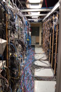
Woah! Don’t get intimidated. There are network tools and knowledge you will gain that will confidently let you troubleshoot similar closets and understand network cable wiring. Most likely it will be neater than that but that's up to you….
It is to your advantage to understand computer network cables and cabling. This section will teach you:
- How to create patch cables and crossover cables (Network Cable Wiring)
- How to test the cables
- How to troubleshoot the computer network cables
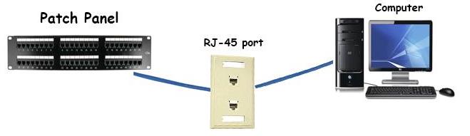
In a typical star topology, a switch is wired with Ethernet cables connecting to the patch panel. These cables are then run to wall plates that have Ethernet ports. From that wall plate, a patch cable is used to make the physical connection from the Ethernet port to the computer or network device. Similar to this:
There is a 100-meter overall length limitation of the cable run from the closet to the networking device. As you learned in the previous section, CAT5 cable has a speed of 10 Mbps or 100Mbps (Fast Ethernet), CAT5e (Gigabit Ethernet) has a speed of up to 1000 Mbps or 1Gbps.
Category 5 cables are unshielded. They rely on the twisted pair design and differential signaling for noise rejection. This is why it's called unshielded twisted pair cable.
The CAT5/5e/6 twisted-pair cable contains four color coded pairs (8 wires) of 22- or 24-gauge wires that are terminated with an RJ-45 connector. When wiring an Ethernet cable, only 2 pairs (4-wires) are used for data transmission. Pins 1,2,3 and 6 are used on the RJ-45 plug. This means you have 4 extra wires that are not in use and will save you a lot of money and time if you ever need to use those wires because of a damaged existing pair. Also when running the cables, you can use 2 wires for connecting your RJ-11 phone ports.
This means one CAT5/CAT5e/CAT6 cable can transmit data for your network and voice systems.

How to create an Ethernet Cable
The two network cable wiring guidelines defined by the EIA/TIA568-B are T568A and T568B.
What is the difference between T568A and T568B?
These are just two different manufacturer standards used to wire the modular connector hardware.
There is no difference in connectivity between 568A and 568B cables. Which ever one you use is fine as long as both ends are wired identical if you're creating a straight through cable. This means pin 1 on one end connects to pin 1 on the other end of the cable. In other words, if your using T568B the white-orange color wire will be the same on both ends of the patch cable (pin 1). Please see diagram below
A crossover cable would be used when connecting "like" devices. For example: a computer to another computer, a hub to hub, etc. When wiring these types of computer network cables you make one end T568A and the other end T568B. This type of network cable wiring would be handy when you want to link up two switches directly.
Some network devices today use an Auto MDI/MDI-X feature support which allows you to use a crossover cable and the device will auto-switch automatically.
When do you use a straight through patch cable and when do you use a crossover cable?
A straight through cable would be used when connecting:
- Your computer to a switch
- Router WAN port to your DSL/Cable modem's LAN port
- Your computer to a hub
A crossover cable would be used when connecting:
- computer to computer directly
- computer to server directly
- switch to switch directly
- Router's LAN port to a switches LAN port
- Your computer to your printers LAN port
Here is a picture of the colored pairs in an Ethernet cable:

OK.....Ready to begin creating your first Ethernet cable?
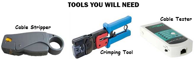
1.) Measure the cable to length, add about seven inches extra and cut the wire. In case you make an error later on, you will have extra wire to redo the termination.
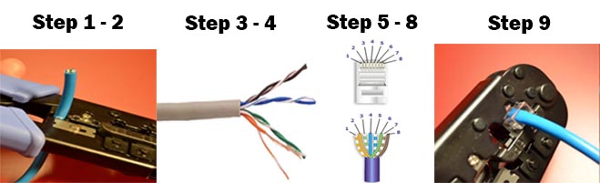
2.) Strip approximately ¾ inch of the cable jacket from the end of the cable using a cable stripper. The cable insulation is removed by rotating the cable stripper around the wire until the wire jacket is loose and can be removed easily.
3.) Inspect the wires and make sure the blade from the stripper did not nip the wires. If they did then repeat step 2.
4.) Remove all the twists in the cable pairs.
5.) Pair your wires with one of the diagrams from above. 568B is the most popular one. If you’re not sure then I recommend you use 568B.
6.) Align the wires and clip them so they are even.
7.) Insert the wires into the RJ-45 modular plug.
8.) Push the wires into the connector until the ends of each wire can be seen through the clear end of the connector.
9.) Use a crimping tool to crimp the wires onto the RJ-45 plug. Insert the RJ-45 plug into the crimping tool and squeeze the handle on the crimping tool all the way until it clicks and releases.
10.) Repeat these steps for the other end of the patch cable. (If you want to create a crossover cable then wire one end 568A and the other end 568B)
Test the cable!
Last step is very important because you don't want to install a bad cable and find out later on that you have to re-wire it again. Network cable wiring should not be a headache after you do the installation once.
The link (point from one cable termination to another) and the full channel (consists of all the link elements from the switch to the wall jack) must satisfy minimum attenuation loss and near-end crosstalk (NEXT) for a minimum frequency of 100 MHz.
Attenuation defines the amount of loss in signal strength as it propagates down the wire.
NEXT - crosstalk is what you occasionally hear on the telephone when you can barely hear another conversation. NEXT is the measure of the level of crosstalk.
Use the cable tester to measure these and ensure the new cable is up to specifications.
With the cable tester you will be able to troubleshoot any network cable wiring issues and ensure your network is running at great speed.
Part 1 - Ethernet Introduction - What is Ethernet?
Part 2 - Computer Network Cables (You are here)
Move on to the next section to learn the Wireless Networking Basics....
Return from Computer Network Cables to Computer Networking Basics
Return from Computer Network Cables to homepage of Computer Networking Success
"Didn't find what you were looking for? Use this search feature to find it."

1
Did You Like This Page?
Share This Page
Laptop Repair Video Course Click Below!


 |
 |
 |
 |
 |
Networking Basics - Certifications - Windows 7 - Windows 8 - Home Network Setup - Wireless Setup :: About - Contact - Search
Copyright © 2013 Computer-Networking-Success.com
New! Comments
Have your say about what you just read! Leave a comment in the box below.